the Creative Commons Attribution 4.0 License.
the Creative Commons Attribution 4.0 License.
 | 22 Apr 2020
Leaking recharge mechanism in the multi-layer aquifer system of a typical land subsidence area in Beijing
Kunchao Lei
Fengshan Ma
Jiurong Liu
Yong Luo
Wenjun Cui
Yi Zhou
He Liu
Xinghui Wang
Miaozhuang Tian
Long Zhao
It is of great significance to reveal the mechanism of land subsidence to further find out the mechanism of leakage flow in multi-layer aquifer systems and the water-release compression of weak aquifers. In this paper, conditions of groundwater leakage flow are expounded, and the initial hydraulic gradient calculation formula in the aquitards are deduced. The data of Tianzhu Land Subsidence Monitoring Station are selected to preliminarily discuss the leakage flow mechanism of the multi-layer groundwater system and water-release compression of weak aquifers. The results show that, firstly the weak aquifer layers in the shallow strata above 91.32 m in Tianzhu Land Subsidence Station are all in the state of unidirectional drainage consolidation, and the water heads in the upper strata are higher than those in the lower strata. However, the hydraulic gradient between the two adjacent aquifers is smaller than the initial hydraulic gradient in the weak aquifer layer, so no leakage recharge effect is generated. Secondly, the water level of the two adjacent aquifers in the deep formation below 91.32 m shows a continuous downward trend, among which the weak aquifer is drained and consolidated on both sides, and the pore water head in the middle of the weak aquifer is the lowest. Although the strata has a large amount of compression, no leakage recharge phenomenon occurs. Thirdly, in a multi-layer aquifer system, when the head difference between adjacent aquifers is small and there is a thick viscous layer between them, it is difficult for the upper aquifer to overcome the shear strength of the bound water in the weak aquifer below, leaking recharge barely occurs.


Leakage refers to the seepage flow from one aquifer (system) through the weak permeable layer/aquitard to another aquifer (system). It is generally believed that when there is a head difference between adjacent aquifers in a multi-aquifer system, leaking recharge will occur as water in the high-head aquifer seeps through the weak aquifer (viscous layer) to the low-head aquifer. However, even in the case of water head difference caused by changes in aquifer head, as the weak aquifer (viscous layer) between adjacent aquifers is in a saturated state, the pores are filled by bound water with poor permeability, thus the pore water release or enter process is very slow, resulting in sluggish water head changes accompanied by processes of releasing or absorbing water in viscous layers.
Many experts and scholars have studied the leakage mechanism and/or the water-release compression in viscous layers. A series of tests were carried out by Cao et al. (2006) on the response relationship between water-release compression, water absorption and the occurrence of leakage recharge in undisturbed clay samples with different lithologies using laboratory test methods. The results indicated that the fluctuation of water level in the aquifers causes the rebound of water absorption or dense pressure release of the adjacent viscous soil layer, and only after then does the stage of water absorption in the viscous layer or occurs concurrently with water release. But the occurrence of leakage obviously lags behind the changes of water head between adjacent aquifers. Niu (1987) discussed the three necessary conditions for the leakage flow between aquifers and calculated the leakage flow by using the long-term water level and settlement observation data. Zhang (1980), Zhu (1991), Sun (1992), Guo et al. (1995), Wu et al. (2006), and Zhang et al. (2009) have discussed the leakage recharge of groundwater and the consolidation process of viscous soil layers in multi-layer aquifer systems.
Based on previous studies, the conditions of groundwater leakage are analyzed and the formula of initial hydraulic gradient existing in weak aquifers are deduced in this paper. Taking Tianzhu Land Subsidence Monitoring Station in the Beijing plain district as an example, a preliminary study on the leakage recharge mechanism of a multi-layer groundwater system in a typical land subsidence area and the water-release compression of a weak aquifer is carried out. It provides a theoretical basis for further revealing the mechanism of land subsidence in the alluvial-diluvial plain of Beijing, clarifying the composition of groundwater exploitation and evaluating the stratified groundwater resources.
Beijing is located in the northwest edge of the North China Plain. The terrain is generally high in the northwest and low in the southeast. The southeast of Beijing is a plain area. The Quaternary strata in the area are composed of alluvial fans and sedimentary depressions formed by five water systems, with typical characteristics of alluvial proluvial plain (Cai et al., 2009).
The aquifer system in the Beijing plain area gradually transits from a single aquifer to a multi-layer aquifer system from northwest to southeast, and can be vertically divided into three main aquifer groups. The first aquifer (The phreatic and shallow confined aquifer) comprises the Holocene (Q4) and upper Pleistocene (Q3) alluvial and diluvial deposits The second aquifer (middle and deep confined aquifer) is a middle Pleistocene (Q2) formation, it has a multi-layer structure with medium coarse sand as the main lithology with some of it containing gravel, and the deepest layeris buried at a depth of around 300 m. The third aquifer (deep confined aquifer) is a lower Pleistocene (Q1) formation with a multi-layer structure, mainly composed of medium coarse sand and gravel, and the bottom boundary is a Quaternary basement (Zhang et al., 2008).
The occurrence and development of land subsidence are closely related to the compressibility of soil. According to the physical and mechanical properties and burial depth conditions of soil, it can be divided into three main compression layer groups in the Beijing plain area. The first compression layer group (Q4 + Q3), widely distributed in Beijing plain area, is the Quaternary upper Pleistocene alluvial facies, alluvial lacustrine facies silt, cohesive soil layer, and the bottom buried depth is less than 100 m. The second compression layer group (Q2), mainly distributed in the middle and lower part of the plain. It is the silt, silty clay and clay layer of the Middle Pleistocene alluvial proluvial, with the buried depth of the floor less than 300 m. The third compression layer group (Q1), mainly distributed in the sedimentary depression area. It is the Quaternary lower Pleistocene silty clay and clay layer, with the upper plate buried depth more than 300 m (Fig. 1). There is an obvious correspondence between the division of the compression formations and the Quaternary aquifer formation in the Beijing plain area (Jia et al., 2007).
Table 1Main physical and mechanical indexes of compressible strata in The Beijing plain.

Notes: W – water content; ρ – density; e – pore ratio; WL – liquid limit; WP – plastic limit; IP – plasticity index; IL – liquid index; a – compressibility/compression coefficient; Es – compression modulus; Cc – compression index; Cs – rebound/swelling index.
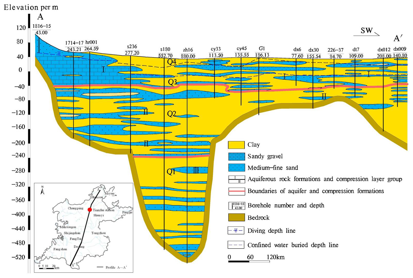
Figure 1Hydrogeological cross-section A–A′ (the location is indicated in the lower left-hand corner).
The occurrence of leaking requires not only a certain head difference between adjacent aquifers (i.e. a certain hydraulic gradient), but also the effective overcoming of the resistance of the weak aquifer (i.e. the shear strength of the bound water in the aquifer).
The smaller the permeability of the weak aquifer layer, the greater the seepage resistance to pore water. Even if there is a certain head difference between aquifers, there may be no obvious leak recharge reflection during limited pumping time. Therefore, only when the head difference of aquifers (hydraulic gradient) can overcome the shear strength of the bound water in the weak permeable layers/aquitards, and produce unidirectional flow in the vertical direction, the phenomenon of leaking recharge may occur (Zhang, 1980; Niu, 1987).
As a consequence, the occurrence of leaking recharge must meet the following three conditions: Firstly, there must be a certain head difference between adjacent aquifers (groups) on both sides of the weak aquifer layer, that is, a certain hydraulic gradient I. Secondly, the above hydraulic gradient I must be greater than the initial hydraulic gradient I0 of the weak aquifer layer (clayey soil). And thirdly, the seepage direction of groundwater in the weak aquifer must be unidirectional flow. Many experts and scholars believe that initial hydraulic gradient I0 exists in clayey soil. The so-called initial hydraulic gradient I0 of clayey soil is the shear strength that can effectively overcome the binding water in the weak aquifer layer, and the hydraulic slope that make water flow in it. The Law of infiltration can be expressed in the following formula:
Where, V is seepage velocity; K is permeability coefficient of the weak aquifer layer; Iis head gradient between two adjacent aquifers; I0 is initial hydraulic gradient; Q is leaking recharge amount.
Experts and scholars have also made special studies on the calculation methods of initial hydraulic gradient in cohesive soils (Zhu, 1991; Sun, 1992), which mainly include two methods: the field measurement method and the use of long-term groundwater level observation data to determine I0. In this paper, we use the field measurement method to determine I0.
When drilling wells in viscous soil, the stable water level will increase correspondingly with the increasing depth of the drilling (hole) (Fig. 2). According to previous experience, the relationship between water level rise and well depth increase is as follows:
As the seepage line in homogeneous cohesive/viscous soil is in the vertical direction, as four points d, c, b and a shown in Fig. 2, so the hydraulic gradient I between any two points can be calculated.
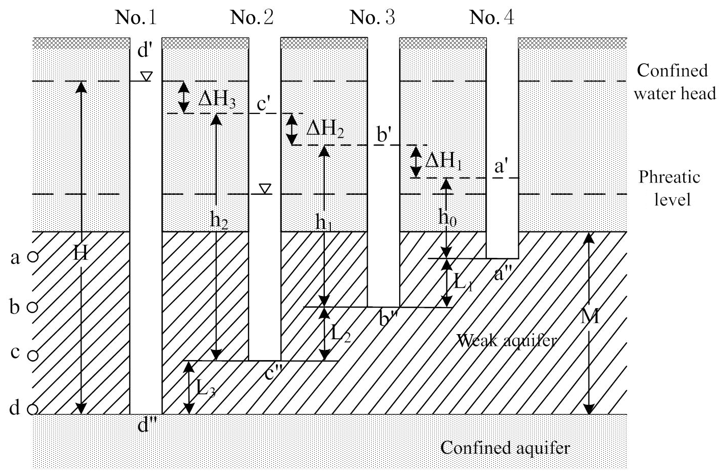
For example, the hydraulic gradient between two points d and c is , if L is the distance higher than the aquifer upper plate at any point, h is the pressure measurement height at this point and H is the pressure measurement height at the aquifer upper plate then the general formula can be obtained:
When the water level in each well (hole) is stable, if minimal evaporation is ignored, then there is no drainage path, and no water from the lower confined aquifer seeps into the well (hole), thus . Since K can't be zero, therefore I=I0.
According to the stable water level measured in wells (holes) of different depths in clayey soil, Eq. (2) can be used to calculate the initial hydraulic gradient when a confined aquifer is replenished by overtopping flow or groundwater infiltration.
Long-term water level and settlement observation data from 2006 to 2017 of the Tianzhu Land Subsidence Monitoring Station located in Shunyi District, Beijing are selected for analysis in this paper. The Tianzhu Land Subsidence Monitoring Station was built in 2004, and it is located in the Houshayu Quaternary sedimentary depression, with a thickness of more than 800 m.
Over these years, along with the excessive exploitation of groundwater in this region, land subsidence continuously develops, with a cumulative settlement of 468.474 mm by the end of 2017.
There are multi-class settlement monitoring facilities built in this monitoring station, including one bedrock marker (burial depth of the bottom 833.02 m), 10 layered markers (burial depth of the bottom 2.40, 35.43, 48.50, 64.50, 82.30, 102.00, 117.00, 148.49, 218.89, and 238.10 m respectively), 6 dynamic underground water level observation holes (location of water filter pipes at 27.50–31.00, 59.30–63.40, 85.70–91.30, 120.00–146.80, 208.30–217.60, and 298.80–308.00 m respectively), and 3 pore water pressure observation holes (7 monitoring layers at 22.00, 39.50, 71.00, 78.50, 96.50, 106.00, and 112.50 m respectively).
Since the pore water pressure probes buried in weak aquifer layers in the Monitoring Station were only placed in a shallow position (120 m), this study mainly used various monitoring facilities up to 120 m depth to conduct a comprehensive study, aiming to further clarify the leaking recharge mechanism in multi-layers groundwater aquifer system and the problem of pressure release in the weak aquifer layers (Fig. 3).
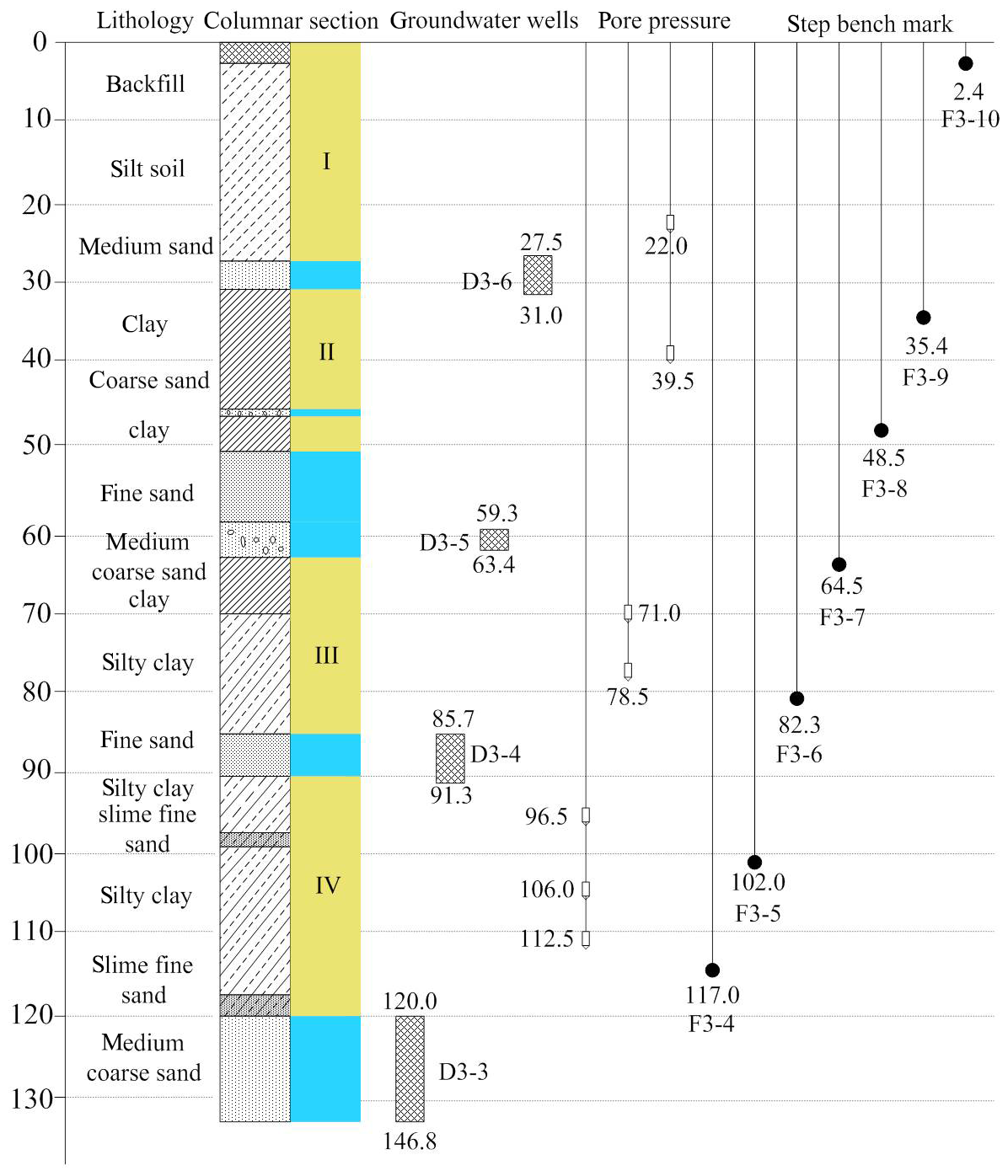
Figure 3Layout of monitoring facilities above 120 m at the Tianzhu Land Subsidence Monitoring Station.
4.1 Leaking recharge problem in the formation of section 27.48–63.44 m
The stratum in this section consists of two aquifers (D3–6 and D3–5) and one aquitard (clayey soil layer II). The water level of aquifer D3–6 has been relatively stable since 2005–2017, showing obvious seasonal fluctuation characteristics. This is mainly due to the shallow buried depth of the aquifer, which is easy to be supplied by the outside world, and the exploitation amount of the aquifer is very small, which has remained relatively stable for many years, the maximum water level elevation is 8.33 m, and the multi-year water level variation is only 0.06 m.
Since 2006, the water head of Aquifer D3–5 shows a continuous downward trend, with the maximum water level elevation of −4.37 m and the minimum −8.89 m, thus the water level decreases by 4.52 m. According to years of observation data, the hydraulic gradient I between two adjacent aquifers (D3–6 and D3–5) is calculated to be 0.70–1.16. Because there is only one pore water pressure gauge buried at 39.5 m in the aquitard (II) between two adjacent aquifers, in calculation of the aquitard (II) initial hydraulic gradient I0, the lower aquifer of upper plate (burial depth 50.37 m) is taken as a reference point in the calculation process, and then the aquitard (II) initial hydraulic gradient is calculated. Through calculation, the initial hydraulic gradient of the aquitard (II) is 1.70–2.47 m. Therefore, although there is a certain water head difference between two adjacent aquifers D3–5–6 and D3, the hydraulic gradient between them is less than the initial hydraulic gradient of the aquitard, which means that it cannot overcome the shear strength of bound water in it. Thus it does not meet the conditions of leaking recharge. In this formation no leaking recharge occurs.
This conclusion can be proved by the pore water and stratified settlement beacons long-term observation data buried in the aquitards (Fig. 4). Among them, the bench mark F3–9 ranges from 35.4 m depth to 48.5 m depth, and the cumulative compression amount is 12.42 mm since 2006. Although the monitoring layers show continuous compression, the pore water head at 39.5 m depth has been in a relatively stable state from 2006 to 2015, with an insignificant downward trend year by year with only seasonal changes, and until 2016 it declined significantly. This implies that before 2016, the pore water in the aquitard continues to discharge, causing compression deformation of the soil mass.
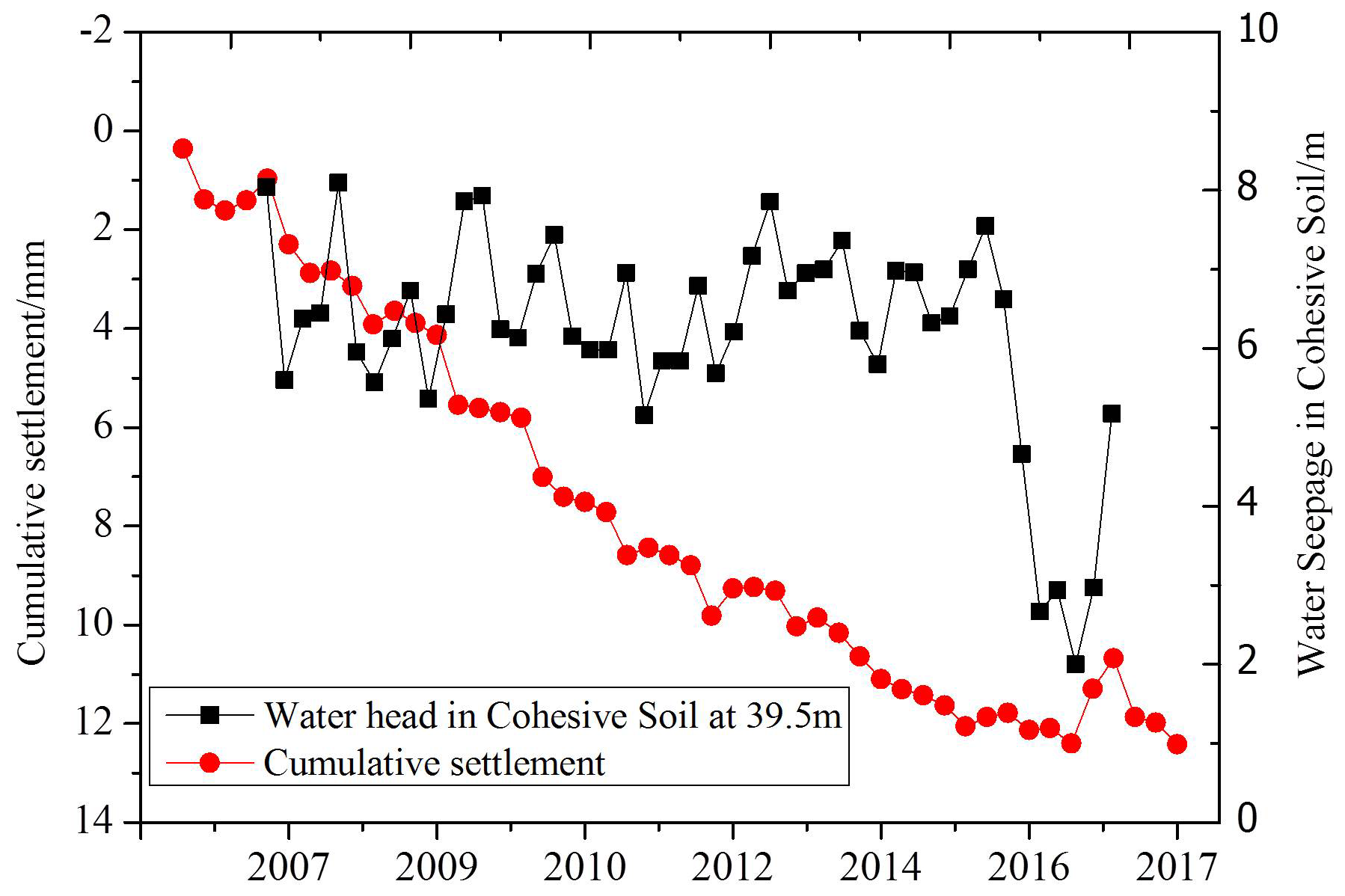
Figure 4Comparison of accumulative settlement and pore head 39.5 m change of step bench mark F3–9.
However, the reduction of pore water head in the aquitard has not been affected to the point of 39.5 m. Since 2016, the water head has only begun to decline, but it has not reached the top of the aquitard. Therefore, the above observation results indicate that the decrease of D3–5 water head in the underlying aquifer only affects the lower part of the aquitard (below 39.5 m), but not the upper part. No leaking recharge from aquifer D3–6 to D3–5 is possible by this time.
4.2 Leaking recharge problem in the formation of section 50.37–91.32 m
The formation also contains two aquifers (D3–5 and D3–4) and one aquitard (cohesive layer III). And the variation characteristics of water head of aquifer D3–5 have been described previously. Since 2006, the water head of the aquifer D3–4 has shown a continuous downward trend, and in 2017 the water head level dropped to −13.15 m, and the multi-year water level decreased by 8.37 m. According to years of observation data, the hydraulic gradient I between two adjacent aquifers (D3–5 and D3–4) is calculated to be 0.18–0.39. Since two pore-water pressure gauges are buried at 71.0 m and 78.5 m depth respectively in aquitard III between two adjacent aquifers, the initial hydraulic gradient of aquitard III is calculated by using the pore water head between these two points. The initial hydraulic gradient of aquitard III is calculated to be 0.97–1.95. Although there is a certain head difference between the aquifer D3–5 and D3–4, and the water level elevation also shows the characteristics of unidirectional drainage, as a result of a thick aquitard existing between two aquifers, and the aquifer hydraulic gradient I is less than I0 of the aquitard, in this formation no leaking recharge occurs either.
4.3 Leaking recharge problem in the formation of section 85.71–133.57 m
The formation is composed of 2 aquifers (D3–4 and D3–3) and one aquitard (sticky soil layer IV). The water head variation characteristics of aquifer D3–4 have been described previously. Water head of aquifer D3–3 has also shown a continuous downward trend since 2006, showing obvious seasonal fluctuation characteristics. In 2006, the water head elevation was −6.66 m, and in 2017, it dropped to −18.30 m, resulting a decrease of 11.64 m.
In aquitard III between the two adjacent aquifers, pore water pressure gauges are buried at 96.5, 106.0 and 112.5 m depth respectively, and the pore water head was −5.23, −23.69 and −7.90 m respectively in 2017. From the water head elevations at each point, the pore water head in the aquitard at 96.5 m is higher than that in the upper aquifer D3–4, as well the pore water head at 112.5 m in the aquitard is higher than that in the lower aquifer D3–3. Moreover, the pore water head at 106.0 m is the lowest, which is located in the middle of the aquitard, showing the same characteristics from years of monitoring data.
This shows that the upper part of the aquitard (IV) releases water to the upper aquifer D3–4, while the lower part of the aquitard (IV) continues to release water to the underlying aquifer D3–3, that is to say, the aquitard is in the state of drainage consolidation on both sides, and the stratum is continuously compressed.
According to the monitoring results of the bench mark F3–5, the accumulated compression amount of 102.0–117.0 m stratum from 2006 to 2017 was 95.447 mm. Therefore, according to the groundwater leaking conditions, leaking recharge does not occur in this section either.
4.4 Other Leaking recharge problems between aquifers
According to the Tianzhu Land Subsidence Monitoring Station data, strata below 133.57 m mainly include two aquifers D3–2 and D3–1, as the head differences are about 2–3 m for many years, and there are dense thick clay/viscous soil between them, the hydraulic gradient is quite small. Due to the lack of a corresponding pore water pressure probe in the stratum below 120 m, the initial hydraulic gradient I0 of cohesive soil cannot be calculated by data. But its engineering geological properties are much better known than for the upper stratum and stratum below 200 m. It is in the over-consolidation state, so its value must be greater than the hydraulic gradient I of adjacent aquifers. In addition the water levels of the two aquifers both show trends of continuous decline, within which the viscous soil is drained and consolidated on both sides. Therefore, it does not meet the three conditions of leaking, thus it is impossible for the formation below 133.57 m to produce leaking recharge or backwater recharge.
5.1 Conclusion
In this paper, three conditions of groundwater leaking recharge are expounded systematically, and the aquifer initial hydraulic gradient I0 calculation formula is deduced. By using multi-layer groundwater system on-site data in the Tianzhu Land Substance Monitoring Station in Shunyi District of Beijing, questions on the leaking recharge mechanism and the aquitard water-release compression have been preliminary discussed, our study finds that:
Aquitards shallower than 91.32 m in the Tianzhu Land Subsidence Station are all in unidirectional drainage and consolidation state, and the water head in the upper strata is higher than in the lower strata. However, the hydraulic gradient I between the two adjacent aquifers is smaller than I0 in the aquitard, there is no leaking recharge effect.
For strata deeper than 91.32 m, the water level of two adjacent aquifers shows a continuous downward trend, the aquitard is drained and consolidated on both sides. Though the pore water head in the middle of the aquitard is the lowest and the formation compression is larger, no leaking recharge occurs.
In a multi-layer aquifer system, when the water head difference between adjacent aquifers is small and there is a thick viscous soil layer between them, it is difficult for the upper aquifer to overcome the shear strength of the bound water in the aquitard below it, leaking recharge barely occurs.
Thirdly, In a multi-layer aquifer system, when the head difference between adjacent aquifers is small and there is a thick viscous layer between them, it is difficult for the upper aquifer to overcome the shear strength of the bound water in the weak aquifer below.
5.2 Outlook
It is of great significance to reveal the mechanism of land subsidence to further find out the mechanism of leakage recharge in multi-layer aquifer system and the water-release compression of weak aquifers, and to clarify the composition of groundwater resources exploitation and the evaluation of stratified groundwater resources.
However, due to the complexity of the stratigraphic sedimentary environment in the Beijing plain area, relevant research data should be further supplemented in the follow-up work, long-term observation data in multiple land subsidence monitoring stations should be used to find out the replenishment and leakage status of groundwater in different geological units, the lag time and effect of cohesive soil consolidation drainage in strata with different lithology and thickness should be clarified step by step, and to explore the composition of exploitation of deep groundwater resources and the migration rules of groundwater pollution sources in the multi-layer aquifer system, all these scientific problems are the future research directions for authors to be further studied.
The data used in this article, because it involves some sensitive monitoring data, cannot be disclosed to the public temporarily according to the relevant requirements of the unit.
FM, JL and YL put forward many valuable opinions to the paper. WC, YZ and HL help process relevant monitoring data. XW, MT and LZ help typesetting and drawing related illustrations.
The authors declare that they have no conflict of interest.
This article is part of the special issue “TISOLS: the Tenth International Symposium On Land Subsidence – living with subsidence”. It is a result of the Tenth International Symposium on Land Subsidence, Delft, the Netherlands, 17–21 May 2021.
I am very grateful to the reviewers and editors of this article for their valuable suggestions. Thank you.
This research has been supported by the Beijing Outstanding Young Scientist Program (grant no. BJJWZYJH01201910028032) and the National Natural Science Foundation of China (grant nos. 41831293, 41930109 and 41771455).
Cai, X. M., Luan, Y. B., Guo, G. X., and Liang, Y. N.: 3D Quaternary geological structure of Beijing plain, Geology in China, 36, 1021–1029, 2009.
Cao, W. B., Wang, L., Gong, J., Zeng, Y. J., and Wang, D. C.: Experimental research on saturation characteristics of clay under variation in water levels, Hydrogeology & Engineering Geology, 12, 101–106, 2006.
Guo, Y. H., Shen, Z. L., Zhong, Z., and Wang, D. S.: The property of deep-lying groundwater resources in Hebei plain and its reasonable evaluation in view of land subsidence, Earth Science-Journal of China University of Geosciences, 4, 415–420, 1995.
Jia, S. M., Wang, H. G., Zhao, S. S., and Luo, Y.: A tentative study of the mechanism of land subsidence in Beijing, City Geology, 2, 20–26, 2007.
Niu, X. J.: Overflowing replenishment of confined aquifer in Tianjin urban area, Site Investigation Science and Technology, 6, 3–8, 1987.
Sun, J.: Leakage and sticky soil storage related to the evaluation of deep level pore water resource, Geology of Anhui, 3, 46–50, 1992.
Wu, Q., Xie, H. L., Zhao, Z. M., Li, J., and Jin, X. L.: Study on deformation mechanics of aquitard, J. Univ. Sci. Technol. B., 3, 207–210, 2006.
Zhang, A. J., Ye, C., Li, Y., Liu, Y., and Xie, Z. H.: Beijing Groundwater, China Land Press, Beijing, 2008.
Zhang, S. X., Liu, Y. W., and Sheng, Y. R.: Mechanism analysis on water level of confined well in groundwater overdrafting area, J. Seismol. Res., 32, 339–344, 2009.
Zhang, Z. Y.: On the geological theoretical problems of surface suspended rivers and the integrated hydrodynamic problems, Geological Publishing House, Beijing, 1980.
Zhu, W. W.: The research on the hydraulic properties and compression properties of leaky aquifer systems, Earth Science-Journal of China University of Geosciences, 1, 95–104, 1991.